All VNAs are equipped with coaxial connectors, but the transmission media used in the latest generation of high-frequency communication devices can include transmission-line devices such as stripline, coplanar or microstrip waveguides as well as new types of coaxial connectors. The interfaces needed to integrate such a variety of components into a compatible test environment inevitably lead to significant measurement errors which cannot be ignored.
In some coaxial cases, non-insertable devices can be handled with a special class of adapter removal calibration; but this is usually not the case for PCBs and on-wafer structures. More generally, de-embedding can be used to remove the effects of the fixtures, adapters, launchers and probes required to execute the measurement.
A number of functions are available beyond the basic calibration and display tools to help post-process the available data in a way that is useful:
Embedding/de-embedding, including the virtual removal or insertion of networks or circuits around a device under test which may represent fixtures, launching structures, tuning elements et cetera.
Reference plane control, which can be thought of as a simpler subset of de-embedding in which transmission-line lengths and losses are removed from the measured data.
Impedance transformation, whereby the data is viewed as if the VNA had been calibrated in impedances other than the standard 50 ohms.
The key concepts for embedding and de-embedding are:
Networks are set up on a per-port basis
Networks used on the two ports are entirely independent
Any number of networks can be cascaded at a given port.
Common embedding tasks are: viewing the results as if a different launch structure were present; viewing the results as if a new matching circuit were being used; and viewing the results as if an added cable length or transmission-line length were used. Common de-embedding tasks are removing the effects of a test fixture; removing the effects of a launch or launching transmission line; and removing the effects of a test matching circuit that will later be physically removed. The latest generation of VNAs incorporate an embedding and de-embedding engine to carry out these tasks.
There are five different types of networks that can be used in these operations: inductive elements, capacitive elements, resistive elements, transmission lines and .S2P-defined, file-based networks.
Dozens of different network extraction and de-embedding methods exist for different measurement environments. One approach is model-based, where it is assumed that a portion of the fixture has a specific circuit configuration (for example, a transmission line, a series impedance, et cetera). However, this approach does not always describe the required network for de-embedding with the necessary accuracy. Because of the complex and incompatible media that may be involved, techniques using multiple calibrations (in different connectors or different media) or techniques using a pair of adapters and fixtures back-to-back are sometimes employed.
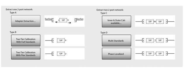
For a standard two-port VNA, four types of extraction techniques are available:
Type A - Adapter extraction: Two full 2-port calibrations are performed; one each with the adapter/fixture attached to one port. A single S2P file describing the adapter/fixture is generated.
Type B – Two-tier calibration with full standards: A one-port calibration is performed, followed by additional standards being measured with the adapter/fixture in place. A through connection is not required, and a single .S2p file is generated.
Type C - Inner and outer calibrations: Full 2-port calibrations are performed at the outer plane (often coaxial or waveguide) and at the inner plane (often a fixtured environment). Two S2P files are generated in this case.
Type D - Outer calibrations using the divide-by-two method: Two adapter/fixture "halves" are connected back-to-back and the combination measured using a single outer calibration. With good matching between the halves, S-parameters can be extracted. Two S2P files are generated.
These four methods of network extraction all require one or even more sets of full calibrations, which is sometimes not practical. As a result, a novel approach for network extraction known as Option UFX (Universal Fixture Extraction) has been developed by Anritsu. This approach adds two more useful methods to the list: Type B two-tier calibration with flexible standards, and Type D network extraction with multiple standards.
Phase-localised network extraction
This technique belongs to a class of approaches that have been termed "partial information techniques" since they make additional assumptions about the fixture to avoid the necessity of a full calibration at the inner plane. As such, these techniques are particularly attractive when the inner plane has a complex structure or geometry that makes it difficult to create many standards for that plane or difficult to accurately model those standards.
There are a number of different ways to use Type D. At least one through interconnect between halves is needed. An additional (different length) interconnect can be used or high reflection standards can be used at the inner plane. As more standards are added, additional information is obtained and accuracy generally improves.
A variation of Option UFX type D known as phase-localised network extraction makes use of knowledge of fixture length (through user entry or model fitting) to better localise mismatches and to enable a more accurate extraction if the fixture is electrically long enough. A single standard (either a line or a reflect/reflect pair) is used along with the assumption that the fixture is electrically long enough (based on the frequency range being used) and the bulk of the fixture mismatch is not too close to the inner plane. If the assumptions are met, this method can outperform the previously discussed Type D variations. Central to this method is the concept of the fixture length as transmission-line like. If the fixture length entry is set to zero, an automatic process (much like auto reference plane delay) will estimate the length.
Sequential extraction – peeling (Option UFX)
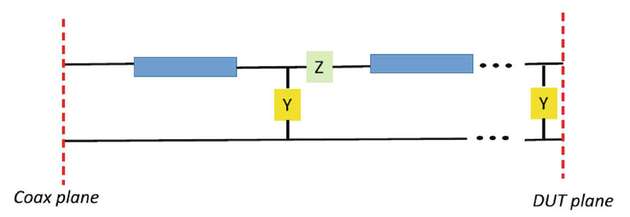
Another method of network extraction known as "peeling" involves modelling the network as a collection of lumped elements. This is particularly popular for electrically small structures (such as on-wafer) or those with runs of transmission line punctuated by electrically small structures (PC boards with isolated vias in transmission lines).
Procedurally, this method works on one lumped element at a time. For each element, a .S2p file is generated that can be de-embedded to allow one to get at the next element. Also, transmission line segments can be separately de-embedded to get between lumped defect areas. The process is based on reflection measurements only and a full calibration incorporating that port must be in force. The basic method accepts as input the location (in time from the reference plane) of the defect area of interest and the type of element to model the structure: shunt admittance (Y) or series impedance (Z).
The premise behind a measurement/modelling approach like sequential peeling is that the fixture can be broken down into simple lumped elements, possibly separated by transmission lines, and that these elements can be found through measurement. The lumped elements might physically be vias, abrupt transitions, line bends, close approaches of nearby metallisation or other structures. The important requirements are that they are electrically small (compared to the frequency range being analysed) and that one can assign a shunt or series nature to them. The sequential peeling approach does not require a net list and is not trying to solve for circuit elements explicitly: rather, it is attempting to come up with a simple model that does a reasonable job of describing fixture behaviour while being able to extract those model elements with sufficiently simple measurements.
Seven different types of extraction available
This article has described a series of techniques for handling and studying the problem of non-insertable devices. Adapter removal is a 2-calibration technique for removing the effects of an adapter from a given calibration setup. Network extraction is somewhat more separable in that it tries to extract the S-parameters of the complicating adapter/fixture so that it can be de-embedded later.
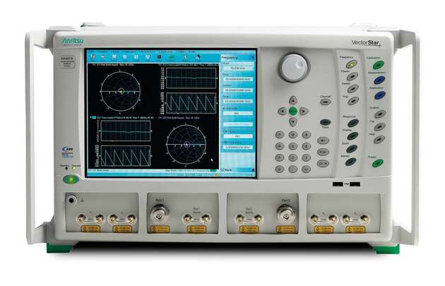
Seven different types of extraction are available in the current version of the Anritsu VectorStar MS4640B vector network analyser. A modelling-based extraction technique using sequential localisation or peeling is also available as an alternative for special cases to overcome the shortcoming of traditional embedding and de-embedding functions. All these methods are also applicable for multiport systems.


